PICK AND PLACE FILE
Overview
Proteus incorporates the ability to produce a file for use as a starting point in setting up automatic insertion machines. Essentially this file lists the component layers, positions and rotations, and you control which columns appear and what they are called so that the result matches the machine you are feeding.
The command is Output Menu > Generate Pick and Place File, which opens the Pick and Place Export dialogue.
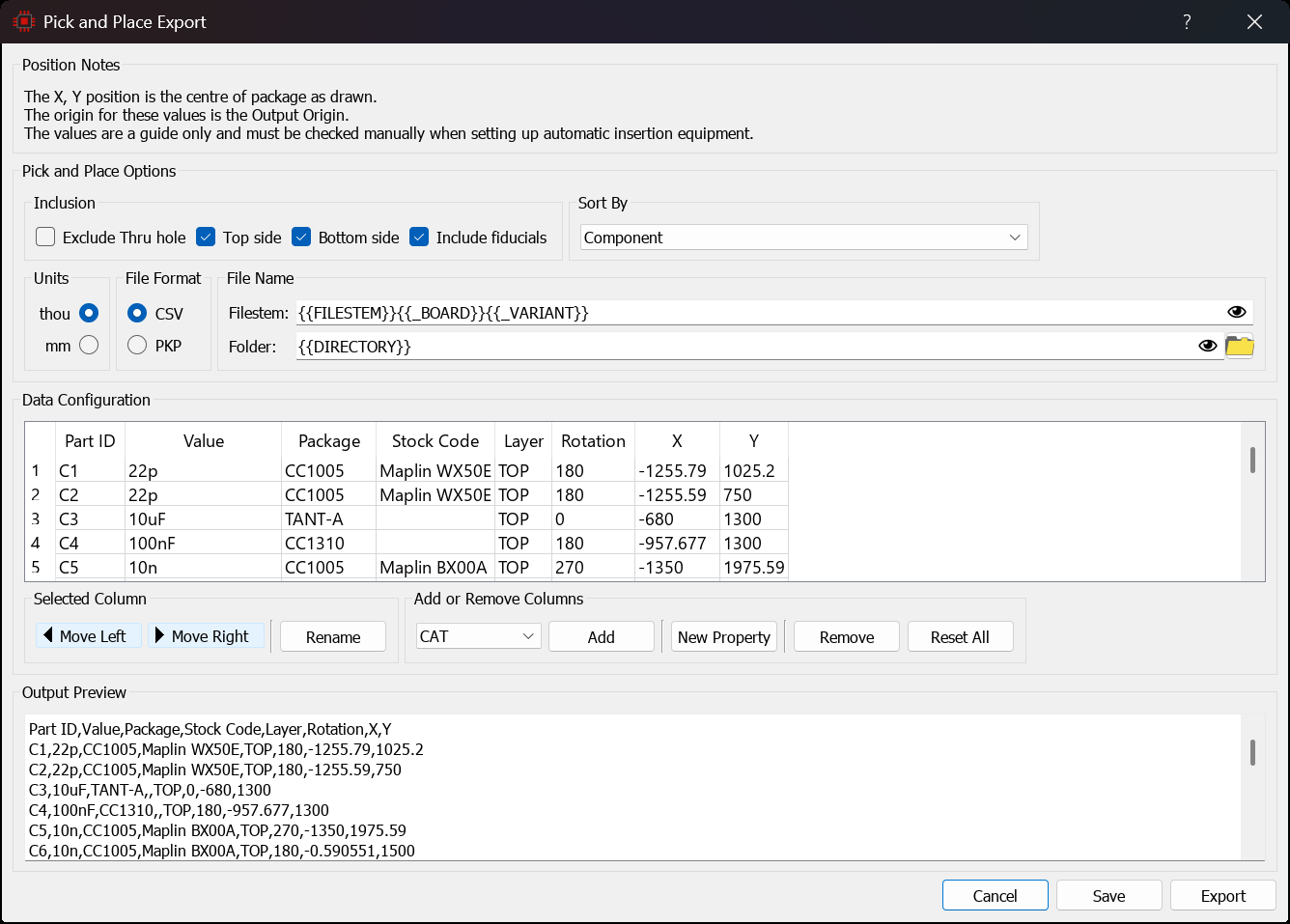
Pick and Place Export dialogue form.
Position Notes
The panel at the top of the dialogue restates the three things that matter about the co-ordinates in the file: the X, Y position is the centre of the package as drawn, the origin for those values is the Output Origin, and the values are a guide only and must be checked manually when setting up automatic insertion equipment.
Pick and Place Options
Inclusion
Exclude Thru hole omits through-hole parts, leaving only the surface mount components that the machine can actually place.
Top side and Bottom side control which side or sides of the board are exported. Both are on by default.
Include fiducials adds the board fiducials to the listing so that the machine can use them for optical alignment. This is on by default.
Sort By
Chooses the order of the rows in the file. The options are None, which keeps the internal database order, Component, which sorts by part reference, and two grouping orders that sort by component and then by value and package name, optionally followed by package size. Grouping by package size suits a machine that is loaded feeder by feeder.
Units
The X and Y values are written in thou or mm. Thou is the default.
File Format
Two formats are offered. CSV writes a plain comma delimited file with a single header row of column titles. PKP writes a Labcenter format listing with a descriptive header block giving the project path, the assembly variant, the field list, the units and the positional notes, and with every cell quoted. CSV is the default and is the format most insertion machines expect.
File Name
Filestem and Folder set where the file is written. The extension follows the format you chose, either .csv or .pkp.
Both fields accept field codes. The default filestem is {{FILESTEM}}{{_BOARD}}{{_VARIANT}}, which names the file after the project and appends the board and variant only when the project actually has them.
Data Configuration
This section is where you shape the file to suit your machine. The grid shows the columns that will be written, in the order they will be written, with a sample of the data in each.
The default columns are Part ID, Value, Package, Stock Code, Layer, Rotation, X and Y.
Selected Column
Move Left and Move Right shift the selected column within the file. Rename changes the column heading, so that a machine expecting Designator rather than Part ID can be fed directly.
Add or Remove Columns
The drop-down lists the component properties available on this design. Add appends the chosen property as a further column, and New Property lets you define a property that is not yet in the list. Remove deletes the selected column, and Reset All restores the default column set and the default headings in one step.
Because the headings travel with the columns, re-ordering a renamed column carries its name with it. Use the Output Preview to confirm the result before you export.
Output Preview
A live, read-only preview of the file that will be written, reflecting every option above. Check it before exporting.
Saving and Exporting
Three buttons close the dialogue.
- Export writes the file and is the command you want once the preview looks right.
- Save stores the configuration without writing a file, which is useful when you are setting up the column layout for a machine you will use again.
- Cancel abandons any changes.
Your configuration is saved with your ARES settings, so the same column layout, sort order and format come back the next time you export.
Notes on the File
A component that is not fitted in the currently selected Assembly variant is omitted from the Pick and Place file entirely, since there is nothing for the machine to place.
There are a number of points that must be appreciated about this file:
- The origin for the co-ordinates is the Output Origin; this is the same origin as is used for the Gerber and Excellon outputs.
- The (x,y) co-ordinates represent the centre of the component package as drawn. This position may or may not correspond to the origin of the component for auto-insertion, but it will be approximately in the correct place. Our understanding is that this is helpful in that it provides a starting point for manual alignment of the placement head.
- The rotations are in anti-clockwise values in degrees relative to the orientation of the package when it was defined. Since there is no standard for default orientations of packages these values may be of limited use unless they can be combined with a translation table that is specific to layout packages including ones you have defined yourself. This is a matter between yourself and whoever is providing the auto-insertion facility.
See Also: